
Under construction
The spectrograph is designed as a white pupil instrument very similar to FEROS and UVES guided by advice from ESO technicians (i.e. Bernard Delabre). A rough drawing is shown as Fig. 1.
The elements seen are
Figure 1. To the left are two off-axis parabolic mirrors. The light enters the fiber unit to the right, goes to the collimator and comes back to a small mirror close to the fiber assembly after being reflected by the Echelle grating in the upper right corner. It is then directed towards the second parabolic mirror at the lower left and is directed towards a large prism. Finally, the spectrum is imaged on the CCD camera at the lower right corner by the camera lenses.
The optical design is shown more clearly in Fig. 2, which show the optical path of the light in more detail:

Figure.2. Raytracing of spectrograph
The fiber input unit is mounted on the side of the telescope adaptor opposite the standby CCD camera. A special unit has been placed in the adaptor so that when the pickup mirror is brought in for the fiber, the fiber entrance is imaged onto the standby camera. This makes it possible to position the object very precisely on the fiber and monitoring the guiding even for quite faint objects. The optical scheme of this arrangement is shown in Fig. 3:
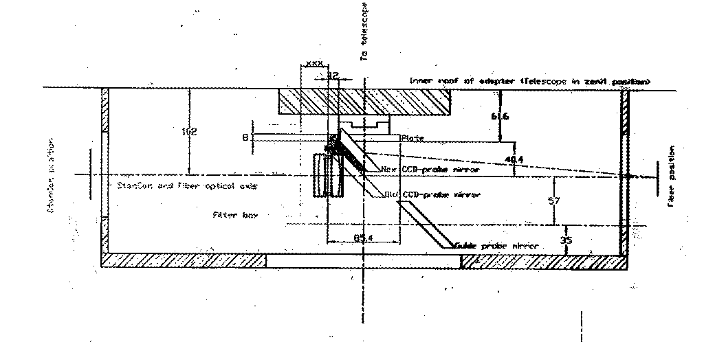
Figure 3. The fiber viewing setup in the adaptor. Light enters from the telescope at the top and hits the pickup mirror and is reflected towards the right. Part of the light is reflected from the front of a small front lens to the input fiber. A doublet forms an image of the fiber entrance on the standby camera to the left.
![]()
There is a possibility to choose between different fibers. At present only one fiber runs from the telescope to the spectrograph. Polymicro delivers a range of fibers with different diameters. The figure shows the response of different types for a 50m fiber, long enough to connect the adaptor with FIES in the new room in the new building at the bottom of the telescope.
The fiber is mounted in a tube with a small lens glued to the frontend.
The tube can be fixed in
a V block with clamps. It is easily mounted ot removed from the V block
and the position repeats very
precisely and therefore at the same time the postion of the fiber on
the standby camera.

![]()
Figure 4. Lights enters from the left and enters the
fiber or is reflected towards the standby camera..
The small lens converts F/11 to F/7.5.
The fiber has a length of ~5 m and is combined with a fiber
from the calibration unit before entering the spectrograph. At the
output end of the fiber a small lens converts the focal ratio to match
the collimator.
The entrance slit (88micrometer, transmitting 75%) is evaporated on the
output lens and no alignment is
needed. The principle is illlustrated in Fig. 5.

Figure 5. The fiber optics showing the focal ratio changes and the slit compared with the fiber.
After the lens follows a shutter and as the last item a sliding prism, which can take out the light to a small diode photometer. These elements can be seen in Fig. 6. All pieces are easily installed and removed. They are clamped into a V block mounted on the optical table. No slit alignment or other adjustments are needed.

Figure 6. The optical fiber enters from the right and
has the output lens glued on. The hatched
part next is an electronic shutter. Next follows the sliding prism,
which can be moved in and out
through computer commands, and the diode photometer. In the future a
more sensitive photometer
and a beamsplit reflecting only infrared light should replace the very
simple system used now.
The second fiber is connected to the calibration unit, which houses
several different lamps. At
present there are the following choices
Each lamp can be selected by rotating a prism by a computer command.
Every lamp can be switched
on and off from the computer, except the thorium lamp. The fiber feed
is placed in a V block compatible
with the block at the fiber input at the telescope. This way the
primary fiber can be placed at the same
position to calibrate the primary spectrum (flatfielding).
Before the fiber entrance a second shutter is placed. This way one can
expose the CCD to different amount
of light from different lamps, making a combined spectrum of different
sources. In addition it is possible
to divide the amount of calibration light into small doses spread over
the exposure time of the main
spectrum. This permits a better calibration of small wavelength shifts.
The calibration unit is shown in Fig. 7.
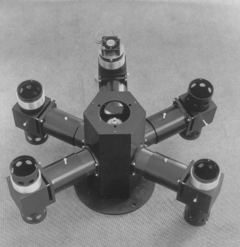
Figure 7. The calibration unit with 5 different
lamp positions. The fiber mount was not yet mounted
when this photograph was taken.
The CCD camera is a Liquid Nitrogen cooled system with a Brocam
controller. The design chip is
Loral 2Kx2K thinned CCD with a pixel size of 15 micron. Two amplifiers
A and B are used. Readout
can take place via A or B or using both at the same time. Using one
amplifier the readout time is 80 s.
Reading out in parallel it takes 40 s.
The spectrograph has an inner and an outer enclosure. The inner
enclosure mostly serves as a protection
of the optics against dust. The outer enclosure has a layer of
insulation and serves as a thermal jacket.
Heaters and propellers keeps the interior at constant temperature
controlled by sensors and a thermal
regulation system. Temperatures can be recorded at five different
positions to check the stability and
measure any drift. This is done remotely from the control PC.